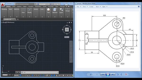

Since we have shown how the G-code is obtained (How it is generated), it remains to be explained how this G-code is used in CNC machining. The following figure shows one generated G-code - Do you recognize some of the G functions we have shown in the table above? After that, it is possible to simulate the tool path and create a CL file which is later post-processed and transformed into G-code. The following four functions refer, respectively, to the selection of machines, tools, operations and work plane.
#Cad for cnc software#
So, first, the CAD model of the part is imported with the "Reference model" function, and then the "workpiece" option defines the workpiece - based on the volume difference between these two CAD models, the software will later generate the tool path.


Looking from the left to the right, all functions are given in the order we have shown in the previous scheme. In particular, the drop-down menu of the "Manufacturing" card is interesting because it contains almost all the functions needed to generate a single G-code. In the picture above we can see the interface of one CAD / CAM software - it is PTC Creo Parametric, version 5.0.1.0. But the procedure in each of these software is similar. Nowadays, there is a large number of CAD / CAM software packages (CAD stands for Computer-Aided Design and CAM stands for Computer-Aided Manufacturing) for programming CNC machines, such as Autodesk Fusion 360, SolidWorks 3D CAD, Solid Edge CAM Pro, GibbsCAM, PTC Creo Parametric, etc. Most CAD / CAM systems define geometry in CNC programs, while other technical information such as grips, basing and clamping, cutting tools and cutting modes are added through an interactive user dialogue with the CNC machine. The integration of CAD and CAM has led to advances in NC programming methodology. CNC programming for processing the above mentioned parts (components). Therefore, it was necessary to use a computer for technical preparation, i.e. Complex programs for processing such surfaces require several thousand blocks (sentences) of which handwriting is very laborious and time-consuming. The geometry of complex parts (used for example in the aircraft, missile, military and other industries) is very complex with second-order surfaces, which require multi-axis machining (3-axis, 4-axis and 5-axis CNC processing). But before that, let's get acquainted with the basic G functions, which we will later recognize in the generated G code. This article refers to today's most used, most productive and most reliable method of programming - programming using CAD / CAM systems. Today, different programming methods are used: Manual, programming in operation, programming using programming languages (here we primarily mean other programming languages such as APT, AUTOPRIT, AUTOPROGRAMER, COMPACT II, etc.) and programming using CAD / CAM systems. This unique program, which controls almost all CNC machines, is called the NC program or better known G-code (This name was given because most functions in this programming language refer to defining the geometry of the part being processed - G functions). Numerous, letters and other symbols arranged according to certain rules and coded in the required form make up the program, necessary for providing the intended functions of the working bodies of the machine. For CNC (Computer Numerically Controlled) machine tools or CNC systems, all information for processing work subject is obtained in the form of numerous, letters and other symbols.


 0 kommentar(er)
